 Rob Kremer

 Chapter 6
 index
index
 Chapter 8
The previous chapter describes the Constraint Graphs program from a design point of view. In contrast, this chapter is far more pragmatic and describes how to use Constraint Graphs to implement several formal and semi-formal visual languages.
The chapter starts with a very simple, semi-formal language, gIBIS (Graphical Issue Based Information System) (Conklin & Begeman 1987). The description of gIBIS serves to introduce the reader to the basic functions of Constraint Graphs. But the gIBIS description does not exercise the system's full capabilities. The more advanced features of Constraint Graphs are illustrated in Section 7.2, which presents an implementation of an extension to Conceptual Graphs (Sowa 1984). Conceptual Graphs has many uses in knowledge representation and natural language representation and has a reasonably large and active user community. Finally, Section 7.3 presents KDraw (Gaines 1991b), which is a visual form of the CLASSIC (Borgida et al. 1989) knowledge representation language. This language presents a real challenge for Constraint Graphs, serving to exercise most of its power and showing some very interesting problems in visual language representation.
gIBIS (Conklin & Begeman 1987) is an acronym for "Graphical Issue-Based Information System". It is a simple visual language used in business decision making. There are several versions, and all are very simple. The language consists of typed nodes and typed arcs only (there are no contexts). The version used in this example has only three node types:
There are also seven arc types. All of them are binary, directed arcs and are limited to connecting only certain node types to certain node types. Table 3 lists the arc types and includes the arc terminal restrictions.
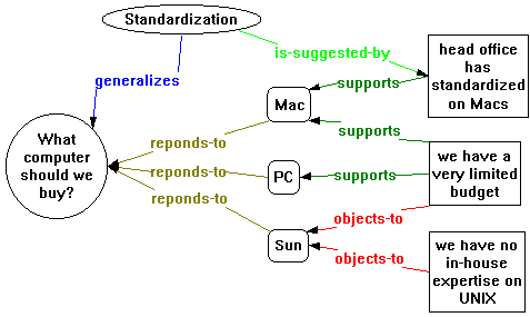
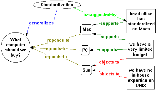
Figure 31 shows a simple gIBIS map, which may be created as part of making a decision about which type of computer an organization is going to buy. In this map, Issue nodes are shown as ellipses, Position nodes are shown as rounded rectangles and Argument nodes are shown as rectangles.
In order to create a Constraint Graph system to support the construction of gIBIS maps, one needs only:
All of this is easily done using Constraint Graphs. The following discussion will follow the reasoning that a visual language designer might go through when constructing a Constraint Graphs gIBIS implementation.
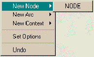
Since Table 3 shows that the questions and is-suggested-by arcs may terminate on any of the three node types, it makes sense to capture the notion of a general gIBIS node (the union of Issue, Position, and Argument). In addition, one might want to capture the notion of a general gIBIS arc, and specify that it must connect a gIBIS node to another gIBIS node. (While the need for a "gIBIS arc" might seem speculative at this point, good reasons for choosing to implement it will become apparent near the end of this discussion.) The gIBIS node is created by left-clicking on the background and choosing New Node|NODE from the popup menu:
After naming the node gIBIS node, the gIBIS arc may be created in a similar way and both arc terminals may be attached to the gIBIS node. This yields the following map:

Both terminals of the gIBIS arc terminating on the gIBIS node serve to restrict the terminals of any gIBIS arc subtype to terminate on components that are subtypes of gIBIS node (see Section 6.4.2).
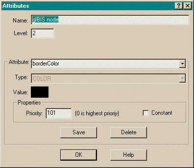
The visual attributes of the gIBIS node and the gIBIS arc are specified using the attributes dialog box. The attributes dialog box for the gIBIS node is shown in Figure 32. The Name box lets the user type in the name of the node. The Level box lets the user specify the level of the component (see Section 6.4.4). Here, level 2 is chosen because "gIBIS node" is not a legal gIBIS node type - it is just a necessary part of the ontology, and must be hidden from the end user. At this early point, the designer realizes certain components must be hidden from the end user, so it is appropriate to choose the leveling structure. A typical breakdown is as follows:
This level assignment suffices for the current purposes. Both the general gIBIS node and the general gIBIS arc are assigned to level 2. The other, concrete, gIBIS types can be assigned to level 3.
The attribute box of Figure 32 is where the user can specify attribute/value pairs. While the user may specify arbitrary attribute names, the following attributes are used by the system for nodes:
All these attributes are set for gIBIS node except for constraints, which is left empty.
The attributes for arcs include all of those for nodes, plus
The attributes are all specified for the general gIBIS arc.
Finally, the actual gIBIS nodes and arcs can be defined. The three gIBIS nodes, Issue, Position, and Argument, are first defined as top-level Constraint Graph nodes, then an isa arc is drawn from each to the general gIBIS node. Immediately after the isa arcs are drawn, the visual attributes (colors, shape) of the nodes changes to match those of the general gIBIS node. But Position and Argument are meant to have different shapes, so the attributes dialog for these two nodes is invoked to change the shape attribute appropriately. These operations yield the nodes in Figure 33.
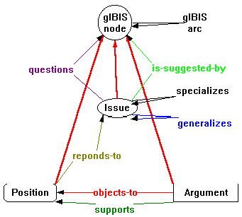
The arcs in Figure 33 are created in a similar way, but to actually show the isa arcs in the figure would clutter up the diagram unreasonably, so a slightly different technique is used. Instead of creating the arcs as generic Constraint Graph arcs, they are created directly as subtypes of the general gIBIS arc. This is done via the background popup menu
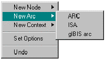
by selecting "gIBIS arc" from the "New Arc" sub-menu. This has the effect of creating the appropriate isa arc in the Constraint Graph, but not drawing the isa arc in the interface. After each arc is created in this way, the end-points are merely dragged and dropped on the relevant nodes, and then the attributes are appropriately modified to complete the definition shown in Figure 33.
An alternative approach to creating a gIBIS arc subtype without a visible isa arc is to select "Arc From/To…" from the node popup menu, which starts an elastic line selection anchored on the node. For example, to create the responds-to arc of Figure 33, the user selects "Arc From/To…" from Position's popup menu. This creates an elastic line anchored on the Position node. The user then drops the elastic line over the Issue node. The system will automatically infer all legal arc types between the nodes and display the possibilities as a menu:
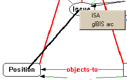
Since a gIBIS arc subtype is desired, it is selected; and the system will automatically draw a gIBIS arc subtype between the two nodes:
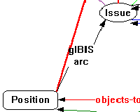
The name of the arc is copied from gIBIS arc,
but the arc can be edited to change its name and any other desired
attributes. In this case the arc will be renamed responds-to.
All of the gIBIS components, except for "gIBIS node" and "gIBIS arc" (which are level 2) should be placed in level 3, since level 3 components will be made visible to the end user. The level 2 components will be hidden.
The gIBIS visual language does not include any notion of subtyping and inheritance. Therefore, end users should be prevented from subtyping any of the nodes or arcs they create. (They must subtype, or instantiate, the basic gIBIS types, but they must not create any subtypes of the instantiated components.) Constraint Graphs provides the functionality to do this through the "ParentOfIndividual" constraint, which is added to each of the level 3 gIBIS components.
Constraints are just attributes in this Constraint Graphs implementation, so the attribute dialog is invoked for each component and the constraint attribute is selected. The "value:" portion of the attributes dialog is an edit button. Pushing the edit button brings up a special constraint editor shown in Figure 34.
The left-hand pane in Figure 34 contains constraints that are currently applied to the component, and the right-hand pane contains all the applicable constraints from the current constraint library. (Nodes, arcs, isa arcs, and contexts all may have different sets of possible constraints.) The "Explain Constraint" buttons are used to get explanations, in both English and in Z, of the meaning of the constraint highlighted in the panes. The "Edit Constraint" button is used to change the parameters of a constraint via yet another dialog.
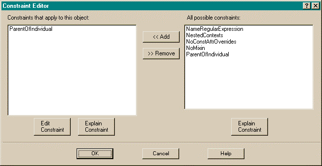
In the gIBIS definition, tagging each level 3 gIBIS component with the ParentOfIndividual constraint will prevent the end user from being able to subclass or instantiate from any sub-gIBIS component.
All that remains to do to create the Constraint Graphs gIBIS model is to hide the unnecessary details from the end user. This is done by using the levels options from the Constraint Graphs options dialog as shown in Figure 35. The "New Menu from Levels" fields select the levels from which the system will infer types. The types in these levels will be the only ones used in the background's (and components') popup menus' "new" sub-menus. They will also be the only types considered when the system must infer the types of arcs (see Section 7.1.2 for an example). Setting the minimum level to 3 prevents the end user from seeing the Constraint Graph base types (level 1) and the gIBIS base types (level 2). Setting the maximum level to 3 prevents the end-user created components (which can only be levels 4 and above, see below) from being displayed in menus or used in type inferences.
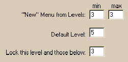
The "Default Level" field in Figure 35 is used to supply a default for the level field of the attributes dialog (Figure 32).
The "Lock this level and those below" field in Figure 35 is used to prevent the end user from editing, deleting, or creating new components in the specified levels. This prevents the user from tampering with the visual language definition, and perhaps inadvertently corrupting the integrity of the language. Components within the locked levels automatically have truncated popup menus: the editing and deletion operations are dropped.
The end user's environment, after all the above is complete, is specialized to the gIBIS semi-formalism. The background menu's "New Node" and "New Arc" submenus are limited to just the gIBIS node types:
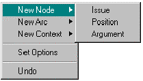
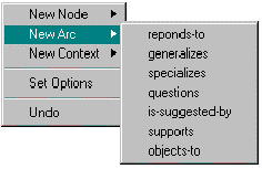
Since there are no contexts in gIBIS, the "New Contexts" submenu is empty. Constraint Graphs allows the creation of new arcs in isolation (unanchored to any nodes at all). These are displayed in the obvious manner:

Any component may be selected by clicking on it, which displays its handles:

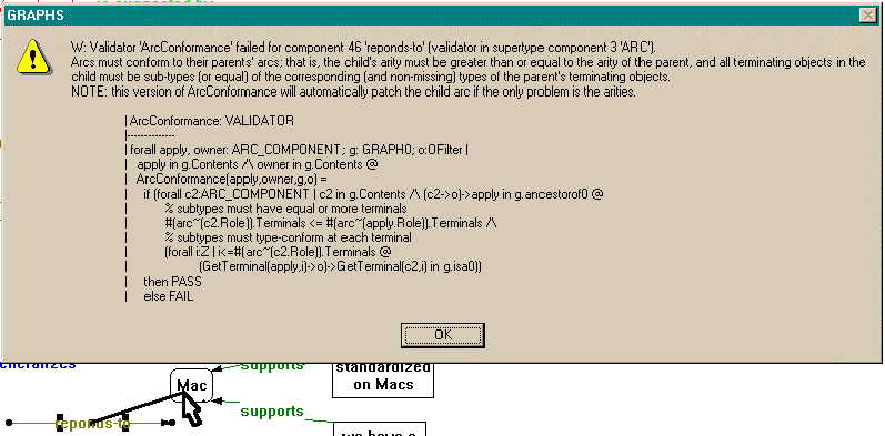
The handles at the terminals may be dragged and dropped on another component to anchor it on that component. But if the terminal is not legal according to its constraints, an error message is displayed and the operation is undone. For example, if the "to" (arrowhead) side is dragged over a Position-type arc (which is not legal, according to the definition), the connection is refused, and an error message is displayed (see Figure 36).
There are also two other ways to create arcs. Both are via the node popup menu:
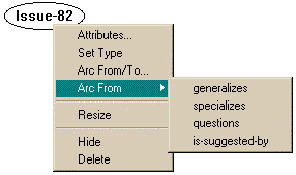
The "Arc From" submenu creates a specific-typed menu rooted at the current node (with the other terminal(s) free. This sub-menu contains only the arc types that may legally be rooted at the target node. In this case, there are only four possibilities.
An arc may also be created by clicking on the "Arc From/To…" menu item, then dragging an elastic line from the current node to another node. The system will infer any legal arc types between the two nodes according to the definition. If there is a unique arc type, an arc of that type will be drawn between the two nodes. If there is more than one possibility, the system will use a menu to query the user for the chosen type, and the arc will be drawn. If there are no legal arc types between the two nodes, an error message will be displayed.
Using these techniques, a gIBIS concept map may easily be created. Figure 37 is an example. Other than dangling arcs, it is not possible to create a syntactically incorrect gIBIS map. If the visual language designer wanted to avoid dangling arcs, then the ad-hoc constraint "noDanglingTerminals" (which is resident in the constraint library) could have been added to the constraints for the "gIBIS arc" arc.
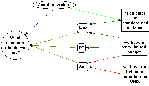
It is now possible to explain more of the rationale behind creating the hidden "gIBIS arc" arc in the first place. Arc-global constraints, such as the "noDanglingTerminals" constraint from the previous paragraph, may be easily added using the "gIBIS arc" arc. Furthermore, other arc-global attributes may be added at "gIBIS arc". For example, if users become very familiar with the arc types, they may be fluent in recognizing the arc types by their color: the arc labels would become quite redundant. Since all the arcs used in the concept map inherit their "connector=directed labeled" attribute from "gIBIS arc", one only need change the connector attribute to "connector=directed" to erase all labels in the concept map. This makes for a far less cluttered concept map (compare Figure 38 to Figure 37). The labels may all be restored by merely changing the one attribute back to its original value.
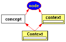
The traditional interpretation is that Conceptual Graphs are bipartite graphs consisting of concept nodes and relation nodes that may be interconnected by directed arcs. Thus, there are only two binary, directed, non-subtype-able arc types: relation-to-concept and concept-to-relation; these support the bipartite nature of the system. In addition there exists a third, binary, undirected arc type, called coreference, which may only occur between two concept nodes. This interpretation is easily modeled in Constraint Graphs (context nodes are omitted here):

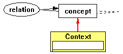
However, an alternate interpretation is that relations are arcs (labeled arcs with an elliptical surround). This interpretation dispenses with relation nodes and the relation-to-concept and concept-to-relation arcs and replaces these with a richly-typed set of n-ary arcs, all of which are a subtypes of the prototypical relation shown in Figure 39. The advantage of this interpretation is that Constraint Graphs can use the intrinsic constraints on arcs to model semantic typing of concepts and relations, restricting the arguments of relations (arcs) to conform to the type hierarchy (as defined by the is-a arcs). Although this semantic extension could be achieved using the first (traditional) interpretation, it would have to be done with parameterized ad-hoc constraints which would be arguably "unnatural" to Constraint Graphs' normal paradigm. It would also be comparatively complex for the end user to specify. Therefore, the alternate, relations-as-arcs interpretation is judged preferable for Constraint Graphs and this is the one that is discussed throughout the remainder of this section.
In the relations-as-arcs model, there are only four primary types of components in Conceptual Graphs: concepts, relations, coreference arcs, and contexts.
Figure 39 is a Constraint
Graphs definition for these four component types. The unusual
features (as compared to the gIBIS example) are:
The important attributes of the Conceptual Graphs definition are
given in Table 4. Since the definition of Conceptual Graphs dictates
that all concepts have rectangular surrounds, the shape attribute
is set as constant for concept. This prevents sub-type
concepts from overriding the attribute and changing the shape:
to do so would interfere with the readability of the map. Likewise,
other shape and connector attributes are also tagged as constant.
Table 4 also mentions one constraint. ParentOfIndividual is applied
to the coreference arc because the coreference arc cannot be specialized
in the Conceptual Graphs framework.
In Sowa's Conceptual Graphs, the ontology (or type lattice) is
not included. Instead, the Conceptual Graphs are assumed to be
accompanied by a separate semantic net that specifies the type
lattice. In contrast, the Constraint Graphs version smoothly
integrates these two separate graph structures into a single graphing
space. This is very natural for the Constraint Graphs structure.
So, a Constraint Graphs implementation of Conceptual Graphs might
be considered an extension of Conceptual GraphsGraphs' graphical notation (but not an extension to Conceptual Graphs theory, since Constraint Graphs does not implement the whole theory -- just the syntax and some of the semantics).
In modeling Conceptual Graphs, the "standard" level
designations need to be extended. In the "standard"
designations, there are two human roles: visual language designer
and end user. In Conceptual Graphs, it makes sense to divide
the end user role further into a user responsible for the semantic
net, and a more tradition Conceptual Graphs user who is only responsible
for the domain. Thus, there are three roles:
Table 5 gives the suggested level settings for each
of the roles.
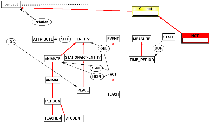
Figure 41 shows an example of a Conceptual Graph as represented
by the Constraint Graphs program. The graph expresses the sentence
"No student read the book the teacher wrote." The Constraint
Graphs ontology used is shown in Figure 40. This ontology is
taken from Appendix B of Sowa's 1984 book (Sowa 1984). The user
who constructed Figure 41 had to add the new types WRITE<ACT,
READ<ACT, and BOOK<ENTITY. The ontology of Figure 40 is
very straightforward. To avoid clutter, the type hierarchy omits
the isa arc between concept and relation and their immediate
subtypes (all of the rectangles and ellipses that aren't at the
"from" end of an isa arc).
The Constraint Graphs program is capable of informing the user
of all legal links between arbitrary nodes. A little experimentation
with this feature quickly points out a few problems with the ontology
which appears in the appendix of Sowa's 1984 book. For example,
Sowa defines the LOC (location) relation as [T]->(LOC)->[PLACE]as
it is in Figure 40 (T is concept in the figure). Constraint
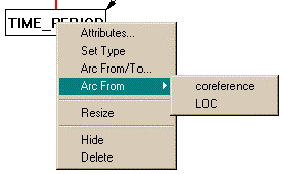
Graphs can infer all the possible arcs that a particular component
may participate in. If the user requests this information for
TIME_PERIOD, Constraint Graphs will infer TIME_PERIOD may be at
the "from" side of either coreferent or LOC:
Clearly, LOC is not appropriate since a TIME_PERIOD
should not have a location. This same problem applies to ATTRIBUTE,
MEASURE, STATE, and all of their subtypes. It would make good
sense to introduce a common supertype for ENTITY and EVENT to
anchor the LOC relationship to, instead of anchoring it to T (concept).
For example CYC (Cycorp 1996) defines "SpatialThing"
as the supertype of "PhysicalEvent" and "PartiallyTangible"
(which roughly correspond to Sowa's EVENT and ENTITY, respectively).
The implementation of Conceptual Graphs covers only the fundamental syntax and some of the
semantics (type lattice constraints) of the Conceptual Graphs formalism. This level of support
presented no particular difficulty to the Constraint Graphs framework, once it was recognized
that relations could be modeled as arcs instead of nodes (as described at the beginning of this
section). However, since much of the syntax of Conceptual Graphs is captured in node labels, a
deeper modeling of Conceptual Graphs would involve several ad-hoc constraints to constrain
the syntax of node labels (which has turned out to be not particularly difficult either – see
Section 7.3.4). Furthermore, label syntax can interact with graphical
syntax in the Conceptual Graphs implementation: an individual marker in a concept node label
should preclude that node being used as a type (as the destination end of an isa arc).
Even this can be handled using ad-hoc constraints, although not particularly elegantly. A more
elegant method of constraining label syntax, and allowing label syntax to interact with graphical
syntax, would be desirable; though it is not clear that such a method exists.
It may be feasible to model the full semantics of Conceptual Graphs using only minimal
extensions to Constraint Graphs. This is described in the "future work" section
(Section 9.3.3).
KDraw (Gaines 1991b) is an interactive, visual, term
subsumption language. It is based on the (textual) CLASSIC language
(Borgida et al. 1989).
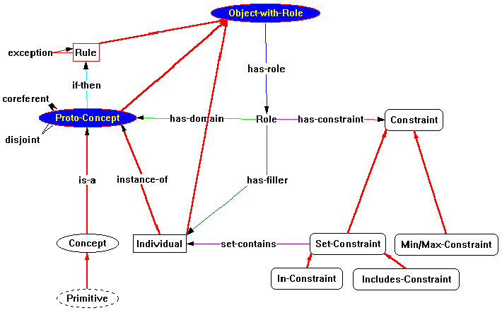
KDraw has 6 main types of nodes, and eleven
relationship types as depicted in Figure 42. All of the KDraw
types (below the heavy line in Figure 42) belong to level 3.
The fundamental KDraw node types are concept, primitive, individual,
constraint, role, and rule. KDraw has eleven relations.
The termination rules for these are shown in Table 6.
Two of the relations are particularly interesting: this is the
first example of subtypes of the isa arc being used in
language definition. The considerable semantics (rules) associated
with the isa arc (isa arcs cannot form cycles, isa
arcs are binary, etc.) are automatically inherited by the subtype
isa and instance-of arcs.
Figure 43 shows an actual Constraint Graphs schema for the component
types in KDraw. Node labels all begin with upper-case letters;
arcs (relationships) are pictured as all lower-case letters.
The surrounds (shapes) of nodes are similar in shape and style
to those used in KDraw. Note that although role has no
surround, it is a node and should not be confused with an arc.
Constraint Graphs allows nodes with no surrounds (as in the present
case) and arcs with surrounds (as in the Conceptual Graphs example)
- it's up to the visual language designer to avoid the potential
confusion that might arise.
Arcs in KDraw are all unlabeled (they are only labeled here for
clarity), and for most part, are binary directed arcs (arrows)
unambiguously distinguished by the (visual) type of their terminal
objects. The cases where arcs types are not unambiguous are those
in which the arc types have both terminals at concepts: isa,
disjoint, and coreferent. These are visually disambiguated
by isa being a directed arc, disjoint being an undirected
arc, and coreferent being a bidirected arc.
Of course, each of the objects shown in Figure 42 must be constrained
to conform to the graphical syntax of KDraw. This is done in
the Constraint Graph schema of Figure 43. For nodes, this is
trivial, for the arcs alone suffice to control the syntax. (Any
nodes could stand alone and unattached without violating any KDraw
rules, though they wouldn't be very meaningful.) The only predicates
applied to nodes are regular expression constraints, which apply
to the labels the end user puts on the various Constraint
nodes. For the most part, arcs can be constrained by merely connecting
their terminals to the appropriate type object. These terminals
are (almost) precisely those shown in Table 6. Complications
in the actual definition (Figure 43) arise due to the need to
introduce additional types:
The next four sub-sections describe these issues in more detail.
Several different, otherwise unrelated, node types
may appear on the "from" side of an arc connecting to
a Role node type. A Rule, Concept, Primitive, and
Individual may all connect to a Role. (But we can
ignore Primitive because it is just a subtype of Concept.)
There is no way to draw the prototype (defining) has-role
arc with three tails and one head without distorting its meaning
(its arity is meant to be two, not four). One way to get around
the problem is to define three different has-role arcs:
has-role-rule, has-role-concept, and has-role-individual.
But this is not very elegant and seems to be contrary to the
"natural" way of thinking about this relation.
A more natural solution is to encapsulate the commonality
between rules, concepts, and individuals: they are all "things
with roles". One can therefore define a supertype of all
three called Objects-with-role. This is exactly what's
done in Figure 43. The new type Object-with-role functions
as the "from" terminal for the has-role arc,
and Rule, Concept, Primitive, and Individual inherit
the ability to have a role from Object-with-role.
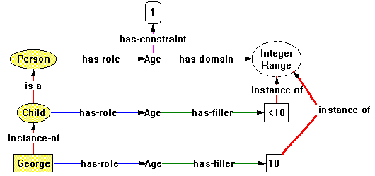
A second problem has to do with natural inheritance.
Note that, in Figure 43, Individual is not a subtype of
Concept, but if the Individual George is
an instance of Child, it might be reasonable for the user
to expect George to inherit the attributes of Child.
In particular, one might expect that the visual attributes will
be inherited: If one shades Person by giving it a fillColor
attribute, then one expects the attribute to be inherited by Child
through the isa arc and then to be inherited by George
thought the instance-of arc, as it is in Figure 43.
Naively, one may consider making instance-of
a simple subtype of isa, but this will not work. If instance-of
were a simple subtype of isa, then George, in Figure 44,
would inherit the ability, for instance, to be associated with
a if-then arc, and this is not allowed (concepts have rules,
individuals do not have rules). Thus, when the user shows the
"Arc from" menu, the choices would be disjoint, coreferent,
has-role, if-then, isa, and instance-of. But the only
choices should be has-role and instance-of.
On the other hand, not making instance-of
a subtype of isa means that individuals will not inherit
visual attributes from the concepts that they are instances of.
It seems there is no solution to the dilemma.
The problem lies in the modeling. Logically, there
are two type lattices involved, not just one. One type
lattice is used to determine arc termination eligibility, and
is called the KR (Knowledge Representation) ontology. The other
is used in attribute inheritance, and is called the domain ontology.
The two ontologies are completely coincident except for the instance-of
arc, which is in the domain ontology, but not the KR ontology.
In the software, this scheme is supported by ontology filters
as described in Section 5.3.
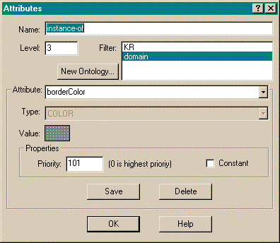
In practice, all that need be done is tag the prototype
instance-of arc with the domain ontology filter
as it is in Figure 45 where only the domain ontology is highlighted
in the filter box. By default, all isa arcs are tagged
with the universal ontology filter (where all ontologies
are highlighted). This effectively solves the problem: attribute
inheritance will occur though instance-of arcs because
they are in the domain ontology, but instance-of arcs will
not be considered when the system is performing type inferences,
such as in arc termination eligibility. Using ontology filters
neatly solves the problem without undue work on the user's part
because different type lattices are normally highly coincident.
By the way, in Figure 43, the instance-of
arc is drawn from Individual to Proto-Concept, and
not to Concept, because Concept has its shape
attribute tagged as constant. If Individual were to inherit
this shape attribute from Concept, it could not override
the shape to be its distinct rectangular shape. Therefore, the
prototype instance-of arc must be drawn between Individual
and some supertype of Concept that does not have a constant
shape - Proto-Concept.
A KDraw isa arc may be drawn between any two
concepts. Naively, one would just draw the prototype KDraw isa
from the prototype Concept, back to the prototype Concept.
But this is a cycle, and cycles are not allowed in type lattices.
Fortunately, there's always a simple way out of the kind of dilemma:
Just create a supertype of the target component, and connect the
"circular" arc between the target and its supertype.
This strategy has been used in Figure 43 to solve the problem
of cycles.
Unlike most node labels in KDraw, constraint labels
must conform to a very specific syntax. There are three types
of constraints: cardinality constraints, subset ("in")
constraints, and superset ("includes") constraints.
Each of these types requires a specific syntax of their node
labels. This is easily accommodated by the ad-hoc constraint
"NameRegularExpression", which is a parameterized function
object in the Constraint Graph's standard constraint library.
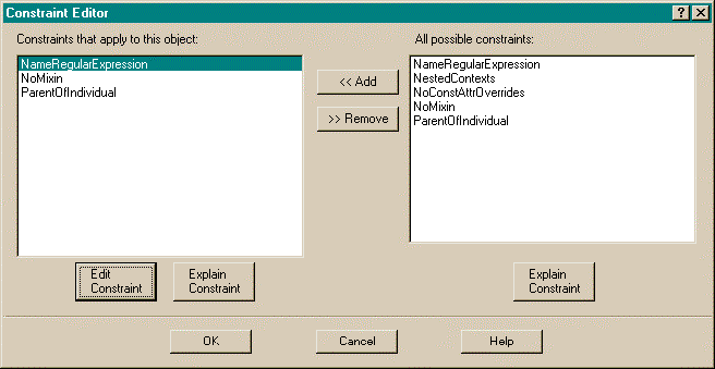
To attach the ad-hoc constraint, "NameRegularExpression",
to a component, the user brings up the component's attribute dialog
box (Figure 45) and selects the attribute "constraints".
The "value" part of the dialog changes to an edit button,
which the user can press to bring up a constraint editor. Figure 46
shows the constraint dialog for KDraw's Min/Max-Constraint
(cardinality) node. To edit parameters of the "NameRegularExpression"
constraint, the user chooses "NameRegularExpression"
from the left-hand panel and then presses the "Edit Constraint"
button. This brings up the NameRegularExpression parameter dialog
box shown in Figure 47.
Ad-hoc constraint parameter dialog boxes are custom
to each constraint. Figure 47 shows the one for "NameRegularExpression".
It is just a multi-line edit box where the user may enter any
number of regular expressions, one per line. The constraint merely
checks to see that the component's name conforms to at least one
of these regular expressions. Figure 47 shows the regular expressions
needed to describe a KDraw Min/Max-Constraint. The first
two expressions are required to accommodate the default names
that might be assigned to the node upon creation. Including these
two expressions allows the user to create the node without immediately
specifying the actual constraint. The remaining three lines allow
the user to express "at most n", "at least
n", and "exactly n" cardinalities,
respectively.
Of the three languages covered in this chapter, KDraw presents by far the greatest challenge to
Constraint Graphs. Although KDraw was studied as a model for the initial theory and
framework design, its actual implementation in the framework caused several iterations back to
the theory and specification stages. For example, the "multiple ontologies" problem
(Section 7.3.2) was unanticipated in the initial design and
was only recognized when testing of the KDraw implementation yielded unexpected results.
This chapter has demonstrated the Constraint Graphs
implementation of a variety of visual languages. These languages
range from the simple to the complex, progressing though greater
and greater challenges for Constraint Graphs. The example languages
serve to demonstrate not only the features of the Constraint Graphs
system, but also several strategies that can be used by visual
language designers to implement languages in the Constraint Graphs
system.
The first example, the gIBIS language for argument, is a very
simple language. Its Constraint Graphs definition is described
in detail, starting with the hidden, top-level abstractions and
how they are used as the core to describe the concrete elements
of the gIBIS language. The language syntax revolves around legal
arc types, and these types are constructed to provide a usefully
constrained user interface for the end user by specializing menus
and specifying type inferences the system may make. Ad-hoc constraints
are used to prevent unwanted subtyping. Constraint Graph's Levels
are demonstrated by using them to hide details of the definition
from the end user. Finally, the outcome of the gIBIS definition
is explained by stepping through some of the operations that an
end-user might perform in creating an actual gIBIS argument.
The second example, Sowa's Conceptual Graphs, is somewhat more
complex than gIBIS. This example is used to describe Contexts,
and to present a more complex example of the use of Levels. The
Conceptual Graphs definition also serves to demonstrate more of
the power of the inheritance relationships: inheritance is used
by the end user to create a domain ontology. In contrast, the
end-user in the gIBIS example merely unwittingly uses a discourse
ontology created by the visual language designer.
The third example, KDraw, is a visual, executable, knowledge representation
language, and is by far the most complex of the three languages.
The KDraw definition demonstrates the use of abstract types to
implement "polymorphic" relations, the use of ontology
filters to create multiple type lattices in the same graph, the
use of abstract types to avoid cycles in type lattices, and the
use of ad-hoc constraints to limit the syntax of component labels.
The implementation of the three concept mapping languages in this chapter serves to both test and
demonstrate the applicability of Constraint Graphs to implementing concept mapping languages.
All of the current features of Constraint Graphs are exercised in the implementation of these
languages. The value of implementing these languages in Constraint Graphs lies not only in the
implementation per se, but also in the understanding of the target language that comes with the
exercise of implementation itself. For example, testing with the implementation of Conceptual
Graphs quickly pointed out some problems with Sowa's published ontology
(Section 7.2) and the implementation of KDraw revealed an
otherwise hidden structure of arc types. While the arc-centric structure of Constraint Graphs can
be seen as unnatural with respect to the original conceptualizations of KDraw and Conceptual
Graphs (which are both node-centric – see Section 9.3.2),
the implementation in an arc-centric paradigm appears to be quite useful and insightful.
concept
node
shape
rectangle const relation
arc
shape
ellipse
const connector
directed labeled const
coreference
arc
connector
plain
const
constraints
ParentOfIndividual context context shape frame const

visual language designer
ontology designer
end user
7.3 KDraw
 Figure 42: A Constraint Graphs model of KDraw. The vertical and
horizontal arcs represent the subtype relation. Objects above
the heavy line are the types of the Contraint Graphs domain; objects
below the heavy line are system types in the KDraw domain.
7.3.1 "Polymorphic" Relations
7.3.2 Natural Attribute Inheritance
7.3.3 Avoiding isa Cycles
7.3.4 Limiting the Syntax of Labels
7.4 Summary
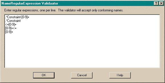 Figure 47: The "NameRegularExpression" constraint parameter
dialog box for KDraw's Min/Max-Constraint constraint
 Chapter 6
 index
index
 Chapter 8
 Constraint Graphs: A Concept Map Meta-Language (PhD Dissertation), Department of Computer Science